Doug Kerr
Well-known member
The old literary expression "wind in the wires" takes on new meaning today in North Texas as a major upgrade of the region's electrical power distribution network unfolds, in part justified in terms of providing for the transport of energy from major wind farms being constructed in West Texas. (At least that's how the transmission company got some federal funding for the project!)
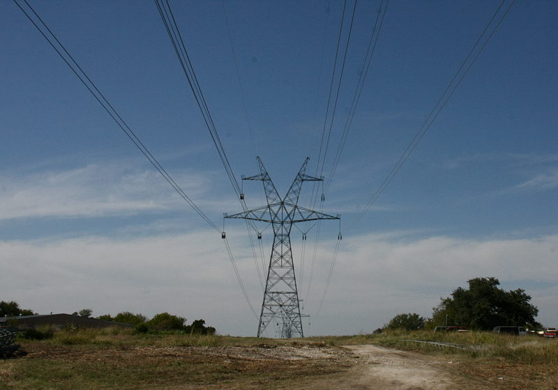
Late in 2009, I reported in detail on the addition of a second 345 kV circuit on a line passing near our home. Now, in another project, about 10 miles to the north, an existing transmission line (138 kV, I think) was dismantled and a new two-circuit 345 kV line is being built in its place.
A couple of Sundays ago, as we drove to our favorite Mexican restaurant, we went past the new line and saw that it was in an interesting state of progress. After we returned home, I took my camera and headed back to capture some of its state.
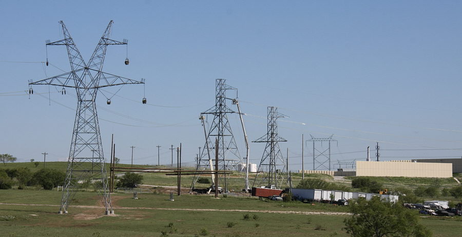
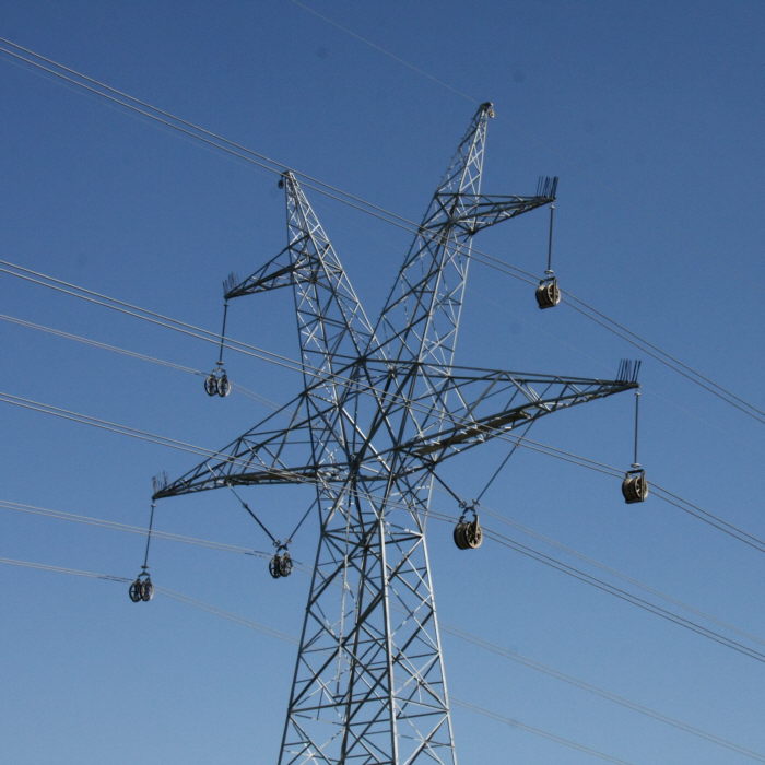
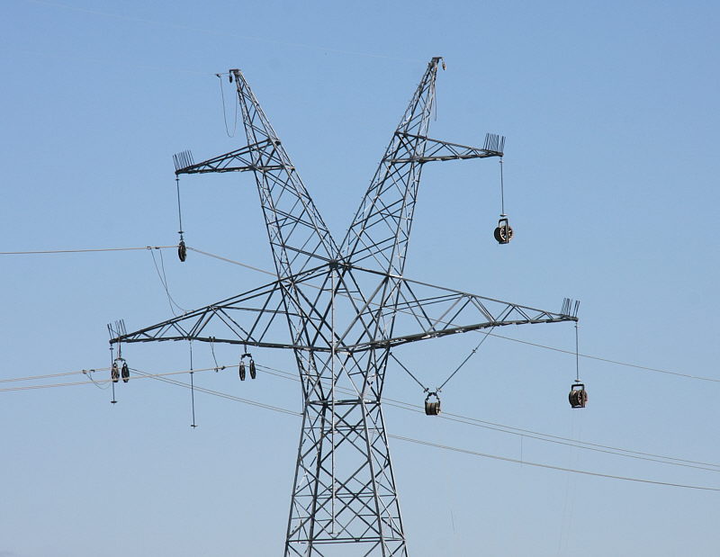
A number of interesting aspects can be seen on a single shot, and I thought I would start my report with that:
Douglas A. Kerr: Wind in the wires 2010
On the left side, the three two-conductor bundles are in place, currently resting in "tensioning blocks", large individual pulleys. There purpose is to allow the conductor strands to move freely when they are brought to their final tension.
Normally, these are suspended from the insulators which, later in the process, will hold the conductors via suspension clamps. (We saw some details of those in my earlier report.) In fact, we see that temporary situation for the upper conductor on the left.
But in this case, for the two lower conductors, the blocks are (at the moment) hung from the gantry arms themselves. My guess is that, given that this tower is one side of a span that crosses a road, this is intended to give the required clearance from the road with the greater "sag" the conductors have prior to being finally tensioned.
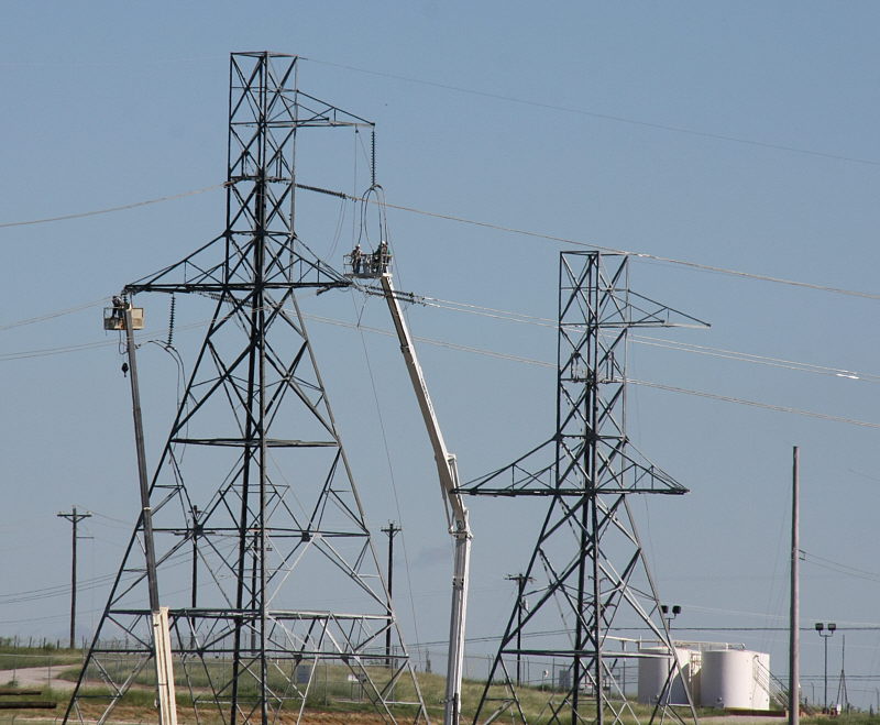
We can see the insulators for these conductors hanging down from the gantry. For the innermost of the conductors, it will be suspended with a "V" shaped arrangement of two insulators, to prevent the conductors from moving too close to the tower proper in the wind (we can see the arrangement on the right). On the left side, the innermost of those two insulators can just be seen along the left side of the tower proper.
We also see flexible conductors used to ground all the circuit conductors. In this case, with no "live" circuits on the line, this is primarily to prevent any possible problem from electrostatic charge or even lightning strikes.
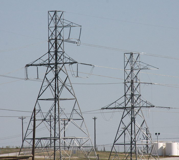
On the right, the conductors have not yet been put in place. For each one, we see a stringing sheave ("dolly") mounted on the insulator(s) that will later carry the conductors.
A braided rope ("sock line") will be threaded through each of these sets of sheaves for the length of the pulling section (several miles). A winch will then use those to pull through steel cables ("hard lines"). Then these will be used to pull the actual conductor bundles through.
This is done on an alternating basis, with the sock line introduced from one end (equipped with a modest-size winch - the "rope machine") and eventually retrieved at that end (after the hard line has been pulled through, with the sock line, by that winch). The conductor will also be fed from that end. The hard line is introduced at the opposite end (equipped with a rather serious winch - the "puller"), and will be retrieved there after the conductors are pulled through, with the hard line, by that winch.
The two conductors of a bundle are pulled through at the same time, attached to the hard line with a triangular adapter called a "leader board". We see one here (from the earlier project), just approaching a dolly:
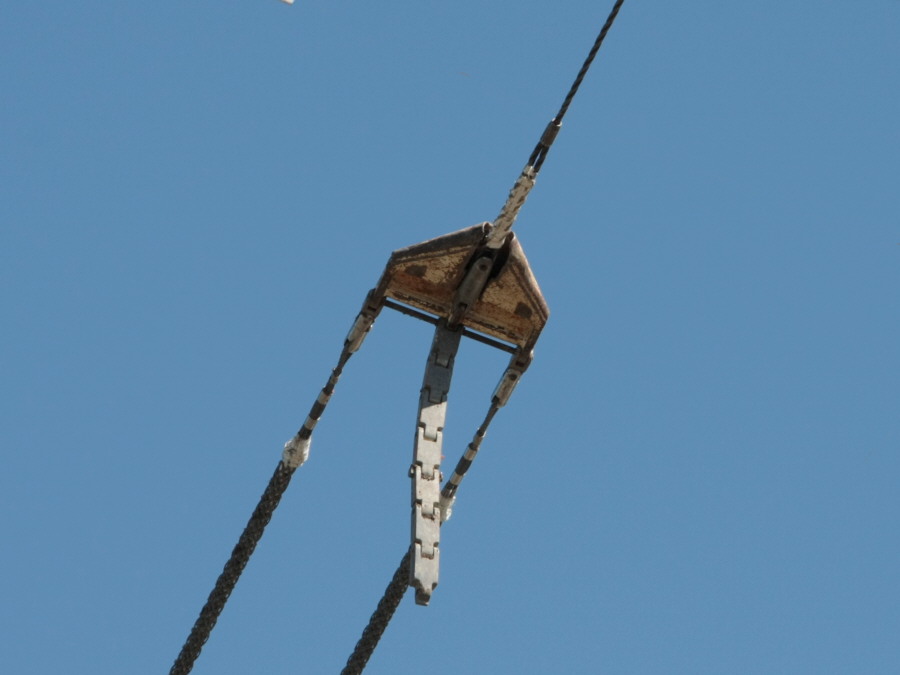
Douglas A. Kerr: Leader board in flight
The segmented "tail", by its weight, keeps the board level so it will properly pass through the dolly. It folds up out of the way as the dolly is traversed:
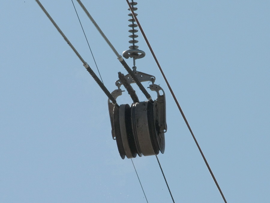
Douglas Kerr: Leader board traversing a dolly
The hard line passes through the deep center groove of the dolly wheel. The two conductors end up in the smaller, outboard grooves.
The term "sock line" is an interesting one. When the conductors are being pulled, usually the pulling line grips the raw end of the conductor with a braided wire sleeve (a "sock"), operating like the fabled toy "Chinese finger puller". (You can see them on the two pictures just above.)
In the days of more modest conductor sizes, the braided rope was equipped with a sock and used to pull the actual conductor, that understandably leading to the term "sock line" for this rope.
Now, when escalating conductor sizes (and longer pulling sections) require a steel line to actually pull the conductor, and of course it is the steel line (or the leader board) that now has the "sock", the braided rope still carries its hereditary name, "sock line".
More later. Now, I have to help Carla and her daughter-in-law get the place ready for a baby shower for our forthcoming great-grandson, Ethan (you have already seen his portrait, in utero).
Best regards,
Doug
Late in 2009, I reported in detail on the addition of a second 345 kV circuit on a line passing near our home. Now, in another project, about 10 miles to the north, an existing transmission line (138 kV, I think) was dismantled and a new two-circuit 345 kV line is being built in its place.
A couple of Sundays ago, as we drove to our favorite Mexican restaurant, we went past the new line and saw that it was in an interesting state of progress. After we returned home, I took my camera and headed back to capture some of its state.
A number of interesting aspects can be seen on a single shot, and I thought I would start my report with that:
Douglas A. Kerr: Wind in the wires 2010
On the left side, the three two-conductor bundles are in place, currently resting in "tensioning blocks", large individual pulleys. There purpose is to allow the conductor strands to move freely when they are brought to their final tension.
Normally, these are suspended from the insulators which, later in the process, will hold the conductors via suspension clamps. (We saw some details of those in my earlier report.) In fact, we see that temporary situation for the upper conductor on the left.
But in this case, for the two lower conductors, the blocks are (at the moment) hung from the gantry arms themselves. My guess is that, given that this tower is one side of a span that crosses a road, this is intended to give the required clearance from the road with the greater "sag" the conductors have prior to being finally tensioned.
We can see the insulators for these conductors hanging down from the gantry. For the innermost of the conductors, it will be suspended with a "V" shaped arrangement of two insulators, to prevent the conductors from moving too close to the tower proper in the wind (we can see the arrangement on the right). On the left side, the innermost of those two insulators can just be seen along the left side of the tower proper.
We also see flexible conductors used to ground all the circuit conductors. In this case, with no "live" circuits on the line, this is primarily to prevent any possible problem from electrostatic charge or even lightning strikes.
On the right, the conductors have not yet been put in place. For each one, we see a stringing sheave ("dolly") mounted on the insulator(s) that will later carry the conductors.
A braided rope ("sock line") will be threaded through each of these sets of sheaves for the length of the pulling section (several miles). A winch will then use those to pull through steel cables ("hard lines"). Then these will be used to pull the actual conductor bundles through.
This is done on an alternating basis, with the sock line introduced from one end (equipped with a modest-size winch - the "rope machine") and eventually retrieved at that end (after the hard line has been pulled through, with the sock line, by that winch). The conductor will also be fed from that end. The hard line is introduced at the opposite end (equipped with a rather serious winch - the "puller"), and will be retrieved there after the conductors are pulled through, with the hard line, by that winch.
The two conductors of a bundle are pulled through at the same time, attached to the hard line with a triangular adapter called a "leader board". We see one here (from the earlier project), just approaching a dolly:
Douglas A. Kerr: Leader board in flight
The segmented "tail", by its weight, keeps the board level so it will properly pass through the dolly. It folds up out of the way as the dolly is traversed:
Douglas Kerr: Leader board traversing a dolly
The hard line passes through the deep center groove of the dolly wheel. The two conductors end up in the smaller, outboard grooves.
The term "sock line" is an interesting one. When the conductors are being pulled, usually the pulling line grips the raw end of the conductor with a braided wire sleeve (a "sock"), operating like the fabled toy "Chinese finger puller". (You can see them on the two pictures just above.)
In the days of more modest conductor sizes, the braided rope was equipped with a sock and used to pull the actual conductor, that understandably leading to the term "sock line" for this rope.
Now, when escalating conductor sizes (and longer pulling sections) require a steel line to actually pull the conductor, and of course it is the steel line (or the leader board) that now has the "sock", the braided rope still carries its hereditary name, "sock line".
More later. Now, I have to help Carla and her daughter-in-law get the place ready for a baby shower for our forthcoming great-grandson, Ethan (you have already seen his portrait, in utero).
Best regards,
Doug