Doug Kerr
Well-known member
In connection with the mechanisms of lenses (focus mechanisms in particular) I will often speak of position encoders, devices that (when digital, as the ones we encounter normally are) give a numeric indication of the position of some moving part, such as a focusing cam or a zoom cam.
Often these use some form of the Gray code for their operation, rather than a straightforward binary encoding. Here I will briefly describe this and why it is useful.
The code is named in honor of Frank Gray, of Bell Telephone Laboratories, Inc., who was responsible for an important exploitation of it (it had actually been used earlier). In his patent application for that system (1947; issued 1953), he lamented that there was no name for the code it used. (Well, we fixed you, Frank, didn't we!) [I studied that system during my graduate training at Bell Telephone Laboratories in 1959.]
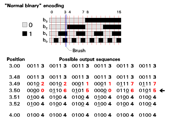
In figure 1, we see schematically an encoder used to report the position of a mechanism to a precision of four bits, using "normal binary" encoding.

Figure 1. "Normal binary" position encoder
We can think of this as having four "tracks", each comprising alternate non-conductive and conductive segments, representing the binary values "0" and "1", respectively. Each track gives the value of one bit of the binary number describing the mechanism position (b0-b3, from "right to left").
A grounded moving "brush" with a finger for each track moves across the encoder as the mechanism of interest moves. At any given position of the brush, each track is either grounded or not, thus delivering electrically a four-bit number to the system.
In the figure, the blue line represents the brush at an illustrative position. The thin red lines represent the ideal positions of the brush for integer values of the mechanism position, ranging from 0.00 through 15.00 (only the integer part is shown on the figure, and indeed this system ultimately deals with positions only to integer precision).
With the brush at (or near) 3.00, the encoded output is 0011, the binary representation of decimal 3. With the brush at (or near) 4.00, the encoded output is 0100, the binary representation of decimal 4.
Consider now what happens as the brush approaches position 3.50 (shown by a dashed red line). Ideally, as it crosses that line, the encoded output would change instantaneously from 0011 (3) to 0100 (4). But of course, the fingers for the bits whose values change at that point (in this case, the three lowest-significance bits) will not all cross the the boundary between non-conductive and conductive segments (or vice-versa) at precisely the same time.
The table at the bottom of the figure assumes that the three fingers make their crossings at three positions separated by exactly 0.01 unit of motion. But even under that tidy assumption they might do that in any of six sequences, shown in the six columns.
At each stage of the scenario shown by a column, we show the binary output, with the bit that has changed underlined, and we show the decimal implication of that binary output.
If we consider the first column, that means that as we approach "3.50", the output is "3" (reasonable; this system only reads to integer precision), and after we have well passed 3.50, the output is "4" (also reasonable). Not reasonable, nor helpful, is the fact that, while traversing the "no-man's land" near 3.50, we briefly get outputs of "2" and "0" (these are sometimes called "flashing outputs".) These are shown in red to remind us that they are spurious.
We can further note that, should the position of the mechanism at rest be at "exactly" 3.50 (indicated by the fat arrow to the right), the decoder output might be 0, 6, or 5, none of them a credible integer-precision proxy for "3.50" (which should either be "3" or "4").
These spurious outputs can completely scramble the operation of a system operating upon the encoded position information.
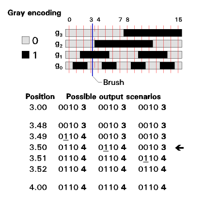
The task of the Gray encoding scheme is to avert this problem. We see it implemented in the same context in figure 2.

Figure 2. Gray code position encoder
It also delivers a binary output, in four bits in this example (we label them here g0-g3), but using a transformation of normal binary encoding (sometimes described as "reflected binary", although that is not at all helpful in understanding its principle). We can see by inspection that, as we traverse the encoder, at any given boundary only one bit changes. For example, at the "3.50" point, only bit g2 changes.
Now in fact, as the brush traverses the region near 3.50, only one actual "sequence" can occur. I show it as "three scenarios" to point out that the is still a small uncertainty as to exactly when that bit will change. But note than in each case, up to that point the output is "3", and after it, it is "4". There are no spurious outputs.
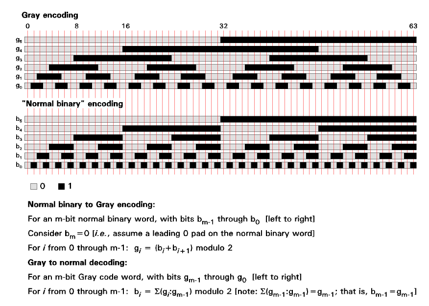
In figure 3, we see a six-bit encoder (64 positions) in both "normal binary" and "Gray code" forms. From it, you can see the unusual symmetry of the gray code.

Figure 3. Gray code and "normal binary" position encoders
At the bottom are two sets of equations, defining the transformations between the two encoding systems. These are direct form, and give the equation for each bit of the destination code.
There are various iterative algorithmic implementations of these transformations that can be more handy in a computer program than canonical implementation of these equations. These are beyond the scope of this note.
There are also other variations of the Gray code useful in various circumstances. These too are beyond the scope of this note.
A short form of the Gray code - often with only 2 bits - is used today for rotary volume controls in audio equipment. There, no absolute position indication is needed, as the operation of the control is incremental, so the short range (used cyclicly) is perfectly usable. The Gray code allows the motion of the control (including its direction) to be unambiguously determined.
Best regards,
Doug
Often these use some form of the Gray code for their operation, rather than a straightforward binary encoding. Here I will briefly describe this and why it is useful.
The code is named in honor of Frank Gray, of Bell Telephone Laboratories, Inc., who was responsible for an important exploitation of it (it had actually been used earlier). In his patent application for that system (1947; issued 1953), he lamented that there was no name for the code it used. (Well, we fixed you, Frank, didn't we!) [I studied that system during my graduate training at Bell Telephone Laboratories in 1959.]
In figure 1, we see schematically an encoder used to report the position of a mechanism to a precision of four bits, using "normal binary" encoding.

Figure 1. "Normal binary" position encoder
We can think of this as having four "tracks", each comprising alternate non-conductive and conductive segments, representing the binary values "0" and "1", respectively. Each track gives the value of one bit of the binary number describing the mechanism position (b0-b3, from "right to left").
A grounded moving "brush" with a finger for each track moves across the encoder as the mechanism of interest moves. At any given position of the brush, each track is either grounded or not, thus delivering electrically a four-bit number to the system.
In the figure, the blue line represents the brush at an illustrative position. The thin red lines represent the ideal positions of the brush for integer values of the mechanism position, ranging from 0.00 through 15.00 (only the integer part is shown on the figure, and indeed this system ultimately deals with positions only to integer precision).
With the brush at (or near) 3.00, the encoded output is 0011, the binary representation of decimal 3. With the brush at (or near) 4.00, the encoded output is 0100, the binary representation of decimal 4.
Consider now what happens as the brush approaches position 3.50 (shown by a dashed red line). Ideally, as it crosses that line, the encoded output would change instantaneously from 0011 (3) to 0100 (4). But of course, the fingers for the bits whose values change at that point (in this case, the three lowest-significance bits) will not all cross the the boundary between non-conductive and conductive segments (or vice-versa) at precisely the same time.
The table at the bottom of the figure assumes that the three fingers make their crossings at three positions separated by exactly 0.01 unit of motion. But even under that tidy assumption they might do that in any of six sequences, shown in the six columns.
At each stage of the scenario shown by a column, we show the binary output, with the bit that has changed underlined, and we show the decimal implication of that binary output.
If we consider the first column, that means that as we approach "3.50", the output is "3" (reasonable; this system only reads to integer precision), and after we have well passed 3.50, the output is "4" (also reasonable). Not reasonable, nor helpful, is the fact that, while traversing the "no-man's land" near 3.50, we briefly get outputs of "2" and "0" (these are sometimes called "flashing outputs".) These are shown in red to remind us that they are spurious.
We can further note that, should the position of the mechanism at rest be at "exactly" 3.50 (indicated by the fat arrow to the right), the decoder output might be 0, 6, or 5, none of them a credible integer-precision proxy for "3.50" (which should either be "3" or "4").
These spurious outputs can completely scramble the operation of a system operating upon the encoded position information.
The task of the Gray encoding scheme is to avert this problem. We see it implemented in the same context in figure 2.

Figure 2. Gray code position encoder
It also delivers a binary output, in four bits in this example (we label them here g0-g3), but using a transformation of normal binary encoding (sometimes described as "reflected binary", although that is not at all helpful in understanding its principle). We can see by inspection that, as we traverse the encoder, at any given boundary only one bit changes. For example, at the "3.50" point, only bit g2 changes.
Now in fact, as the brush traverses the region near 3.50, only one actual "sequence" can occur. I show it as "three scenarios" to point out that the is still a small uncertainty as to exactly when that bit will change. But note than in each case, up to that point the output is "3", and after it, it is "4". There are no spurious outputs.
In figure 3, we see a six-bit encoder (64 positions) in both "normal binary" and "Gray code" forms. From it, you can see the unusual symmetry of the gray code.

Figure 3. Gray code and "normal binary" position encoders
At the bottom are two sets of equations, defining the transformations between the two encoding systems. These are direct form, and give the equation for each bit of the destination code.
There are various iterative algorithmic implementations of these transformations that can be more handy in a computer program than canonical implementation of these equations. These are beyond the scope of this note.
There are also other variations of the Gray code useful in various circumstances. These too are beyond the scope of this note.
A short form of the Gray code - often with only 2 bits - is used today for rotary volume controls in audio equipment. There, no absolute position indication is needed, as the operation of the control is incremental, so the short range (used cyclicly) is perfectly usable. The Gray code allows the motion of the control (including its direction) to be unambiguously determined.
Best regards,
Doug
Last edited:
