• Please use real names.

    Greetings to all who have registered to OPF and those guests taking a look around. Please use real names. Registrations with fictitious names will not be processed. REAL NAMES ONLY will be processed

    Firstname Lastname

    Register

    We are a courteous and supportive community. No need to hide behind an alia. If you have a genuine need for privacy/secrecy then let me know!
  • Welcome to the new site. Here's a thread about the update where you can post your feedback, ask questions or spot those nasty bugs!

The Oliver 23-B sulky plow

Doug Kerr

Well-known member
It is fairly common here in Alamogordo (even "in town") for people to have antique farm implements on display in their front yards. We didn't want to do that (we have a different motif in the front yard), but Carla has been keen to have a farm implement in the back yard. We had in mind perhaps a nice "walk behind" horse-drawn plow.

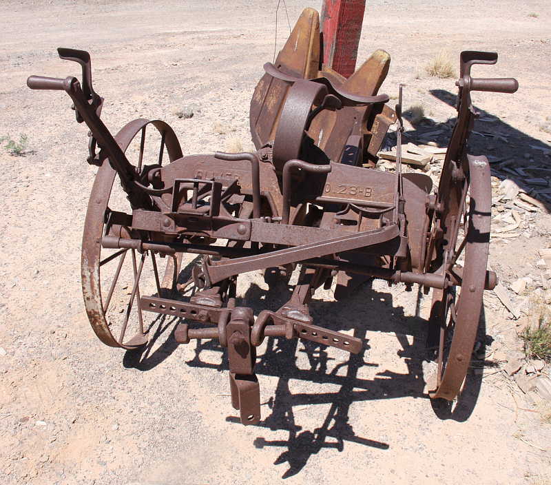
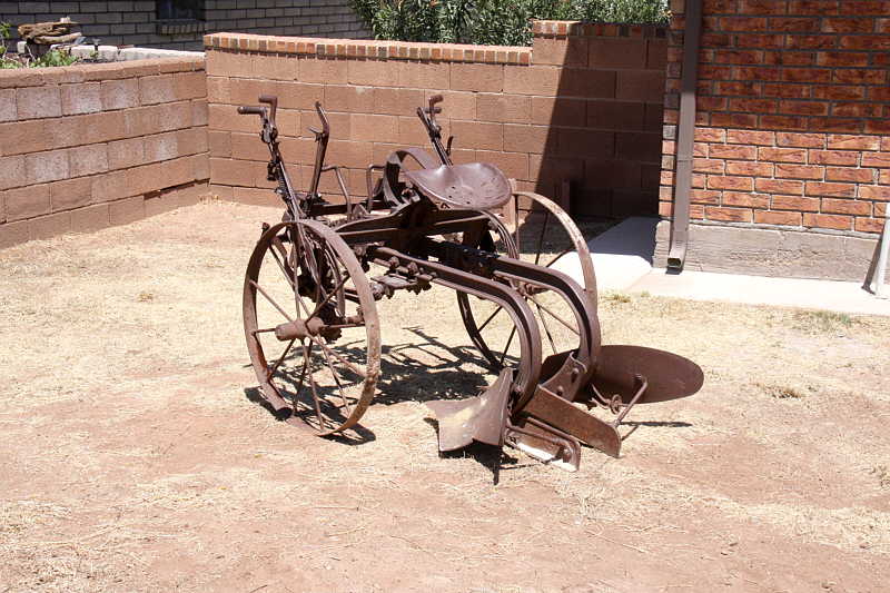
But, as a result of a chain of curious circumstances, we have just completed negotiations with the owner of a presently-defunct antique shop out on the westbound US highway to Las Cruces to acquire a quite elaborate ca. 1920-vintage Oliver No. 23-B "sulky" plow.

In that kind of plow, the operator rides it like a cart, it being drawn by two or three draft horses.

As I'm sure you know, "sulky" normally refers to a light two-wheeled cart drawn by a single horse, such as are used in "harness racing" events.​
This is a reversible plow. In normal plowing of a field, all rows are turned to the same direction, so the earth turned over by one "pass" will fall into the furrow created by the previous pass. And of course a basic plow is made to turn the earth to one side or the other (most commonly, in the US, to the right, but you could order them either way).

But that requires either that plowing be done in a "spiral" pattern for the whole field, or if parallel rows are wanted, the plow has to "deadhead" from the end of each row back to the starting side of the field so it can start the next row in the same direction.

In a reversible plow, there are two bottoms (that refers to the entire earth cutting and turning tool assembly), and at the end of one pass, the plow and horses are turned around, and the operator raises the bottom just used and lowers the other one, which turns the earth in the other direction.

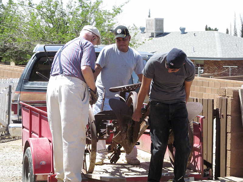
We are now arranging to have the machine hauled from there to our back yard. (It is estimated to weigh over 400 pounds.)

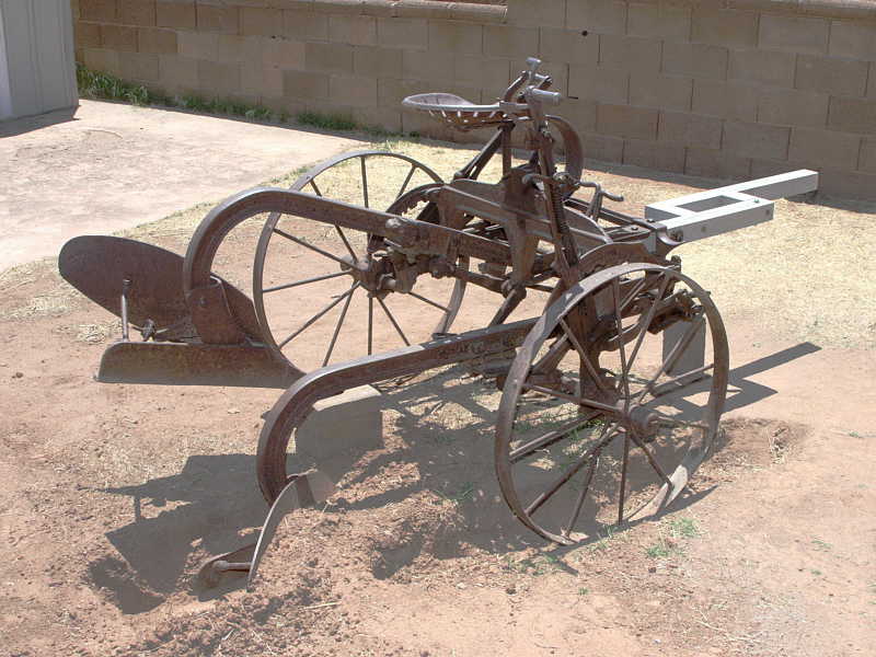
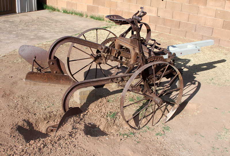
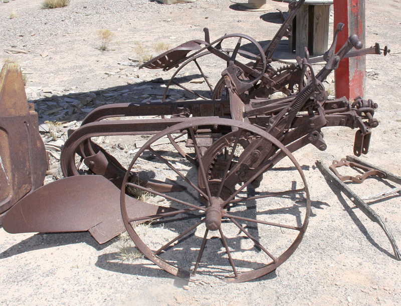
Here we see the machine of interest, in repose under the sign of the antique shop. Its front is to the left.

23-B_F38175-02-S800.jpg


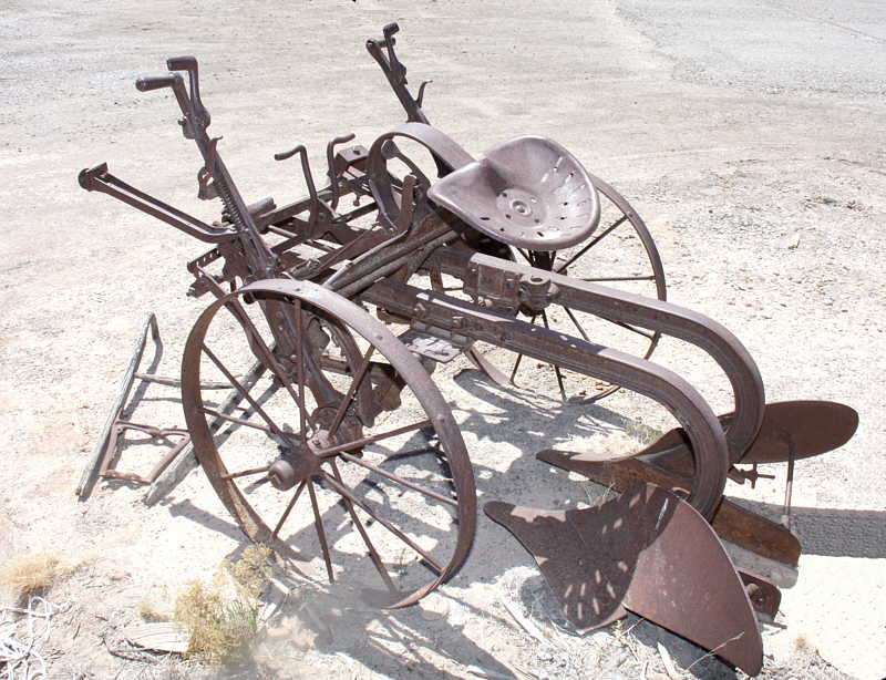
Douglas A. Kerr: Oliver 23-B sulky plow in retirement

You can see to the right the two separate bottoms, here both in the "raised" position, but since the plow is not coupled to any horses - in fact, its wood "tongue" is gone - it has rocked backward so both bottoms are resting on the ground. (You can see that from the attitude of the seat).

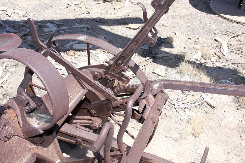
I'll tell you more about the machine and the operation of its many mechanisms a little later. It is a marvel of mechanical engineering.

In the meantime, this link is to a video of a fellow (a plow rebuilding specialist, in fact) plowing a field with an Oliver No. 23-A, an earlier version without quite such refined mechanisms.

http://www.youtube.com/watch?v=--WDmrbNUfs

Best regards,

Doug
 

Asher Kelman

OPF Owner/Editor-in-Chief
This is fascinating. I'd love to see A B&W version.

with the two blad systems, how do the wheel work to align with existing furrows?

Asher
 

Doug Kerr

Well-known member
Hi, Asher,

This is fascinating. I'd love to see A B&W version.

I'll try that.

with the two blad systems, how do the wheel work to align with existing furrows?

One wheel in fact runs in the earlier furrow ("ditch"). As a result, the entire machine leans (substantially) to that side, So the seat can be tilted laterally to accommodate that (there is a latch lever for that motion)!

The horse on the ditch side also runs in the ditch.

The tongue of the plow (which is basically to keep the horses and the plow aimed in the same direction) can be swung from side to side by one of the levers to optimize the lateral position of the horses for each direction of travel. (The lever is hidden in this shot, and the tongue is long-since rotted away - we will replace that.)

By the way, the large levers on each side are to raise and lower each of the bottoms, but they are very heavy. The two little foot pedals (look like bent rods) on the front each engage a mechanism that provides a "power lift" for the bottom on one side or the other, driven by the motion of that wheel.

In either direction of travel, the leftmost horse is called the "near side" horse and the rightmost horse the "off side" horse (those being taken from the traditional names for the sides of a single horse; that is one always mounts a horse from the "near side", and that is the traditional side from which to photograph a horse; for "fancy" horses, the dress of the mane is often done to recognize that).

Often in a two-horse team used for plowing with a non-reversible plow one horse is normally always the near-side horse and the other one the far-side horse. The far-side horse is the guide horse, since he runs in the ditch, which he will do accurately, that being his craft.

If they are then given a reversible plow to pull, on the "reversed" pass (when the ditch is to the left), the far-side (right-hand) horse will often get confused and want to pull to the left to get into the ditch where he has learned he is supposed to run, so there has to be some retraining done. The are many arguments among experts as to the best way to do that.

No reversible plows usually have a larger when on the ditch side or a way to raise and lower one wheel or the other to keep the "chassis" level when the one wheel is running in the ditch (always the same wheel in such a plow.)

Well, in some plows, they can be reversed but not tactically; that is, you might set it up to run right hand or left-hand, but not change between passes.​

No, I knew nothing about any of this four days ago. But you know how it is here!

Best regards,

Doug
 

Doug Kerr

Well-known member
In this video:

http://www.youtube.com/watch?v=LbJ4yHKmcpg&NR=1&feature=endscreen

we see operation of a basic non-reversible sulky plow. It is, not surprisingly, right-hand

Note that on the first pass, there being no ditch for the off wheel to ride in, the plow leans some to the left. Not a big problem for one pass.

The next pass is in the opposite direction (toward us), putting the soil that had been turned up (and then some, to make a new ditch) back into the first ditch. The off wheel is in the ditch.

I don't understand all I should about this getting-started process. (Hopefully one of you farmers out there can straighten me out.)​

On this pass the plow leans too much into the ditch (to our left) (the off wheel set too high). (This is a new plowman.)

The ensuing readjustment of the off wheel has been edited out!

Note then that the plow frame runs level.

Subsequent passes are all toward us, the plow being "circled around" after each pass to what becomes the starting end of the field.

Note that the off horse (Bob, the Belgian - dark chestnut) always runs in the ditch in this session.

The near side horse (on the left), Thomas, a grey Percheron. He always runs "on the land" in this session.

This was at Blue Star Equiculture in South Hadley, Mass.

This was Bob's last pull at Blue Star. He is going to a community-supported agriculture enterprise in upstate New York.

Neat stuff.

Best regards,

Doug
 

Cem_Usakligil

Well-known member
Well, I have learned something new, thanks for that Doug. It is intersting to see how much ingenuity has gone into such a seemingly simple device. Fascinating.
 

Doug Kerr

Well-known member
Hi, gang,

Here are some further pix of our Oliver 23-B sulky plow.

Here we see the machine from the front.

23-B_F38184-01-S800.jpg


Douglas A. Kerr: Oliver 23-B sulky plow from the front

At the center, near the ground, is the point to which the team is actually hitched for draft. The long transverse bolt and the roller arrangement on the yoke that engages it are intended to allow the line of draft to shift as required as the plow and team navigate irregularities in the terrain.

The long transverse bolt is the intended weak spot in the coupling, and it intended to break if the active plow bottom should strike some immovable object (perhaps an unknown boulder in a field firstly plowed.) The alternative (considering that the team comprises two or three draft horses of substantial potency) is that the plow would pitch over, injuring the plowman and perhaps breaking some of its "delicate" mechanism.

Incidentally, the hitch is made directly to the beams holding the plow bottoms (we see their front ends here), as it is of course to the active bottom that the force needs to be most directly applied. The rest of the machine just goes along for the ride.

The two curved-top castings (note the one on our right just beneath the "B" of the model number) are footrests.

The two bent rod articles near the center are foot pedals to engage the "power lift" mechanism (discussed below).

To our left you will see a roughly square receptacle. This is to hold a wood stub tongue. A longer wood tongue is bolted to its side (to our right). The front end of this is connected to the team harness (different ways for a two- or three-horse team). It serves to control the pitch (fore-and-aft tilt) attitude of the plow, and also keeps the plow and horses traveling in harmonious directions.

But so the plowman can precisely adjust the lateral positions of the horse track vis-à-vis the plow track (so that all participants will have their proper body parts in the ditch), the tongue can be swung from left to right by way of a lever acting on the arm we see in the very front (its end to our left waiting to be bolted to the stub tongue when the machine again gets one).

23-B_F38171-01-S800.jpg


Douglas A. Kerr: Oliver 23-B sulky plow from the right side

Here we see the machine from its "off" (right) side.

The nearest long lever, running in a quadrant with unusual teeth, is used to raise and lower the off-side (right) plow bottom. (There is a corresponding setup on the left.)

Part of the complication here (not clearly visible) is the "power lift" arrangement, in which the lever can be moved in the frontward (lifting) direction by a ratchet mechanism powered by the rotation of the adjacent wheel, engaged by the foot pedal we saw earlier.

We note the tiltable mounting of the seat, intended to allow the plowman's posterior to be in a stable orientation even though the plow frame will be tilted substantially to one side or the other (one wheel running in the previously-plowed furrow ditch).

Here we see some of the mechanism close-up.

23-B_F38177-01-S800.jpg


Douglas A. Kerr: Oliver 23-B sulky plow - closeup of some levers

The large lever (its top tilted to our right) is the left-side bottom elevation lever (in its almost full-down position, full forward). The smaller lever (its top tilted way to our left) controls the lateral position of the tongue (as discussed above).

We also see the two curved-rod form pedals for the bottom power lift system.

We see at the very left of the picture the latch on the seat tilt arrangement and the seat spring. It is said that the most comfortable situation for the plowman is walking alongside.

We hope to have the machine in its new home tomorrow morning. The first order of business for Ollie will be essentially an oil bath!

Best regards,

Doug
 

Doug Kerr

Well-known member
Well, Ollie is safely en casa!

Here I am supervising as she is rolled out of the trailer into the back yard (we have a spacious alley behind the house, very helpful for such maneuvers).

23-B_J00768-01-S800.jpg


Carla C. Kerr: Oliver 23-B sulky plow arrives at World Headquarters.​

Here she is in place.

23-B_F38188-01-S800.jpg


Douglas A: Kerr: Ollie in her new home​

Today she got a localized oil bath, to help loosen up all the mechanisms.

Everything is intact, except for the stub tongue and tongue (wood; rotted away years ago), a missing power lift pedal spring, and a small broken handwheel for adjusting the pitch of one of the bottoms.

We plan to exhibit her in situ, with a bottom in the ground and the corresponding wheel in a ditch.

We'll be out of town from Wednesday on, so the restoration work will have to wait until next week.

But we're glad to have her here.

Best regards,

Doug
 
Well, Ollie is safely en casa!

[...]

We plan to exhibit her in situ, with a bottom in the ground and the corresponding wheel in a ditch.

We'll be out of town from Wednesday on, so the restoration work will have to wait until next week.

But we're glad to have her here.

Hi Doug,

Congratulations with the new project. It's looking fine, despite a bit of rust. It'll also make a fine subject for some (abstract) close-up photo's as well. You know, the kind that makes one guess what one is looking at but at the same time gets intrigued by the beautiful shape.

Cheers,
Bart
 

Asher Kelman

OPF Owner/Editor-in-Chief
Doug,

I'd love to see it restored! At least, seal it to stop the rust. Maybe some local fellow, even the casket maker might be able to help rebuild the wooden parts. I'm going to be on the look out for pieces like this to see if one can put together the missing parts. Need a parts catalog first!

Asher
 

Doug Kerr

Well-known member
Hi, Asher,

I'd love to see it restored! At least, seal it to stop the rust.

A good thought, but in this climate the rust will not advance. This has already been outdoors for decades, and the rust is more benign than the rust "finish" on Cor-Ten building members in Chicago.

Maybe some local fellow, even the casket maker might be able to help rebuild the wooden parts.
Fortunately, the wooden parts are very simple. The stub tongue (mounted permanently on the plow, in a swiveling "shoe") is just a rectangular beam. We will be a able to make one on a table saw. My neighbor has one.

The main tongue (runs up to the team) bolts alongside the stub tongue (with two pieces of metal channel as spacers between.)

You can see the arrangement in this drawing from a 1906 patent:

23-B_tongue_pat-02.gif


The stub pole is item H, the main tongue R. (These are sometimes called "poles".)

The entire plow mechanism here is slightly different from the 23-B - it might even show the 11 - but the stub tongue and main tongue arrangement is, so far as I can tell, very similar.

The reason for the two-piece arrangement is that, with a two-horse team, the main tongue is bolted to the left of the stub tongue (and thus falls on the centerline of the plow, as seen in the drawing). For a three-horse team, though, the main tongue is bolted to the right of the stub tongue, and is thus offset to the right, in the proper place to pass between the center and right-hand ("off") horses.

We will probably not make a main tongue at all.

The stub tongue (and thus of course the main tongue) can be swiveled laterally under control of a lever. This allows the track of the plow and the track of the team to be properly aligned (one horse and one plow wheel running in the ditch of the previous furrow).

I'm going to be on the look out for pieces like this to see if one can put together the missing parts.
Thanks.
Need a parts catalog first!

I am trying to get one. I am in touch with two well-known experts on the machine (I earlier gave a link to a video of one of them riding a 23-A). They are both pleased that I have joined their ranks (I won't be as plowman, though!).

This machine is a fine example of the art of the mechanical engineer (but that of course does not make it fine art - If it were, I never could have afforded it). Nevertheless, it could well hang in a museum (much bulkier items are hung, for example, in the Smithsonian Air and Space Museum.)

Best regards,

Doug
 

Asher Kelman

OPF Owner/Editor-in-Chief
Hi, Asher,

.........This machine is a fine example of the art of the mechanical engineer (but that of course does not make it fine art - If it were, I never could have afforded it). Nevertheless, it could well hang in a museum (much bulkier items are hung, for example, in the Smithsonian Air and Space Museum.)

Doug,

As an antique, it might be collected by it's not all that rare, I'd imagine. However, as art, that's dependent on your creative mind and ability to think outside of the engineers box or away from the ploughman's seat! Why not? You have the imagination and advanced knowledge of form. Transpose that to feelings and you're an artist! After all,

The artist, like the engineer, transforms and exports imagination to new or existing, (often transportable), physical form for some function. For art, the resultant work always is conceived with a specific essential extra ingredient: the facility to harness and evoke the human psyche for esthetic experiences, in addition to any utility it might also have.*

Sou, with your new-found, albeit rusted plough, could it then be art? Well it's certainly feasible. You could arrive at some novel concept, positioning or assignment of the piece. Then all the previous identity of the machine would be subsumed in the new identity and purpose you conferred on the work. If the latter was to evoke some reaction in us with esthetic value and move us or provide an environment for our imaginations to wander, recreate and reform what was, is or might be, for example or simply show patterns that were compelling, then yes, indeed it could be art and important too!

If you had a more famous or infamous name, it would be easier!

Asher


* Why am I so damn serious? As I'm always interested by collected things and by the question of, "What our art might be?" Here is a chance to relate to "found objects" and their potential transformation to "art" by some means or other. So I attempt to continually refine my ideas of what the genesis of any art (the stuff offered to us by art dealers, art galleries and art shows), might be. Fine Art, a more exclusive and therefore "expensive" and controversial term, is approached in Will Thompson's very provocative thread here.
 

Doug Kerr

Well-known member
Hi, Asher,

As an antique, it might be collected by it's not all that rare, I'd imagine. However, as art, that's dependent on your creative mind and ability to think outside of the engineers box or away from the ploughman's seat! Why not? You have the imagination and advanced knowledge of form. Transpose that to feelings and you're an artist!

I am always an artist.

And I assure you, my name is indeed well infamous, in many quarters (present company included)!

And Ollie would still be art had I never been born. It is not I that could make her art, any more than a priest can render one a good person. She was made art by a bunch of guys in South Bend, Indiana, before I was born. I might be able to illuminate the nature of her art.

As to Ollie, she will perform her further art in our back yard, a static performance now.

Every furrow that she has turned has been art of the most worthwhile kind. Now how good each one was depends on the plowman (the horses can only do so much to educate the plowman).

Many people have already been moved by her (in the figurative sense that you refer to), and she in the literal sense by many people, and no doubt by many horses, all of them artists. And in fact many have been moved (in both senses) by our choice to acquire her.

The typical response has been: "Well, who would have ever thought that you guys - well, of course you would."

The guy that hauled her here (a landscape artist) just called to see how she is.

Thanks for your observations.

Best regards,

Doug
 

Asher Kelman

OPF Owner/Editor-in-Chief
Hi, Asher,

I am always an artist.

With whole gamut of meanings! :)

And Ollie would still be art had I never been born.

That honesty and commendable. Engineers are, in my experience, less prone to taking credit for other folks work than most of us!

Ollie will live long after all of us, as a fine, rescued and appreciated artful plough that put food on a lot of people's tables.

Asher
 

Doug Kerr

Well-known member
Ollie's rehabilitation is moving along well, and my grasp of her mechanisms as well. One might think that they were primitive and obvious in their working, but they are far from either.

I have just released a 21-page technical article, "The Oliver No. 23-B Reversible Sulky Plow", which I hope gives some insight into this form of art.

Oh, sorry, I forgot where I was.​
It is not yet indexed on The Pumplkin, but is available directly here:

http://dougkerr.net/Pumpkin/articles/Oliver_23-B_plow.pdf

As a teaser, I will cite here the final paragraph of the article:

BENEDICTION
God speed the plow, and the woman who drives it.
–Woman’s Land Army (see figure 3)​
I will have some more pix as soon as she is suitably embedded in the earth.

Best regards,

Doug
 

Doug Kerr

Well-known member
Ollie's rehabilitation is now essentially finished, and we have mated her with the earth in a way that illustrates some basic principles of her operation.

23-B_F38822-01-S800.jpg


Douglas A. Kerr: Ollie in the ground

She is operating here in the "right hand" phase, where the furrow is turned to the right. Accordingly, the right-hand bottom is in the ground, while the left had one has been elevated to ride clear.

We have hand dug two short furrow ditches. One (nearest us and to the right) represents the ditch of the previous-turned furrow. (the "furrow side" horse walks in that, and the "furrow side" wheel of the plow runs in that, as we see above).

The second (furthest from us and to the left, behind the near plow bottom) represents the ditch of the furrow just turned. (The shadows in this shot somewhat obscure the details of the ditches. This was a grab shot done just after the last mechanical work was completed.)

As we see, most of the the right-hand bottom is buried in the earth, doing what it does - tuning the earth from the new furrow into the ditch of the previous furrow (in this case, to the right).

Well, in this case, actually I did that!

That last work, just finished today, was construction of the tongue assembly, primarily of wood. (None of the original tongue assembly survived.)

We see here the tongue assembly.

23-B_F38825-01-S800.jpg


Douglas A. Kerr: The tongue assembly

The major parts of the tongue assembly are northern white cedar. They have been finished with a stain intended to give a weathered, sun-bleached look. The result is not well represented in this image.

We no longer have a table saw nor radial arm saw. We were fortunate to have a specialty lumberyard in Las Cruces (about 65 miles away) cut all the wood parts for us from our drawings. We also no longer have a drill press, but acquired (initially for this project) a very nice portable drill guide that allowed us to drill the many holes needed for the assembly in proper alignment and azimuth.

In the next article in this series, I will discuss the fascinating engineering concepts involved in the tongue assembly.

Best regards,

Doug
 

Doug Kerr

Well-known member
In a machine like the Oliver 23-B sulky plow, it is tempting to think that the various mechanisms are primitive, and that their principles of operation are easily discerned.

In fact this is far from the truth, and considerable research has been required here to ascertain just exactly what is going on with each of them.

The tongue assembly is no exception. There is a lot of very clever engineering involved.

One purpose of the tongue (sometimes called the "pole") is to "steer" the plow so it will trail behind the horse team in a consistent (but adjustable) relative left-right position.

The general relationship needed is this: with the furrow-side horse walking in the ditch of the previous furrow (it's pretty narrow, but the horse knows how to do this), the furrow-side wheel of the plow should also run somewhere in that ditch. The exact relationship depends, among other things, on the furrow spacing that is desired, and of course changes symmetrically between the two directions of plowing.

To allow the proper relationship to be attained, the plowman can swing the tongue from side to side with a steering lever. The lever has a locking mechanism (operating in a notched sector) so the tongue position will be held firmly once set.

The second purpose of the tongue is to control the pitch attitude of the plow (its fore-and-aft "tilt"). For this, the horses serve as "ballast".

This annotated figure shows the assembly and its context.

23-B_F38825-01A2-S800.jpg


Douglas A. Kerr: Ollie's tongue assembly​

With a two-horse team, the tongue extends between the two horses, and it slides through a ring at the center of a bar (the "neck yoke") that extends between the collars of the two horses.

The tongue does not pull the plow. That is done through a hitch from the horses' harness to a draft clevis at the front of the two plow beams.​

For this situation it is necessary that the tongue emerge from the plow at its center.

With a three-horse team, the tongue extends between the center and right-hand horses. For this situation it is necessary that the tongue emerge from the plow about 14" to the right of center.

Accommodating these two different setups is the object of the unusual construction of the tongue system.

The tongue pivot is located about 7" to the right of the plow's center, and extending from it is not the tongue itself but rather a stub tongue about 33" long. The actual tongue is bolted alongside the stub tongue, on one side of the other, with spacers in between to that the tongue is offset 7" to one side or the other of the stub tongue. Thus the tongue (at the plow) will end up either at the center of the plow (for a two-horse team) or 14" to the right (for a three-horse team). We see it here in the two-horse configuration.

In our reconstruction the tongue is not full length, but a shortened version. A full-length one would only have been something to trip over in the back yard.

In the original design of the plow, the spacers were sections of iron channel. We did not care to have such fabricated, so in our reconstruction, we used cedar blocks.

The rear of the stub tongue is bolted to an iron shoe, the front of which pivots on a bolt held in a window-like frame that is actually integral with the right-hand footrest, attached to the plow's front frame. The rear of the shoe has a channel that rides on a circular arc integral with the plow's frame arch. Thus the stub tongue can be swung from side-to-side, yet is rigidly positioned in its vertical attitude (needed so the tongue can control the pitch attitude of the plow.

The steering lever swings the tongue by way of a steering arm fastened to the stub tongue and perpendicular to it, just a little in front of the pivot. There are two braces running from the outer end of the arm to the stub tongue to stiffen the assembly. In the original machine, the rearmost of these has a curved shape and attaches to the stub tongue near its rear (under the shoe).

This brace has a second function: it passes through a slot in an extension of the left-hand footrest, and thus serves to hold the free end of the steering arm in a consistent vertical position, in turn preventing the tongue from twisting.

We did not have either original steering arm brace, and I did not care to have the curved rear brace fabricated. So we replaced it with a short "stub", just long enough to pass through the locating slot and do its second job. The front brace follows the original design.

This figure shows the variation in tongue azimuth under control of the steering lever.

23-B_Tongue_swing-01.jpg


Douglas A. Kerr: Steering motion of the tongue​

Carla was at the controls for this series, discreetly clearing for each shot. (Her purple overalls were in the wash.)

God speed the plow, and the woman who drives it.​

Overall, it is quite a piece of engineering!

We are pleased to have Ollie again intact and in the ground, where a plow belongs.

Best regards,

Doug
 

Doug Kerr

Well-known member
These figures, adapted from one from the manufacturer, show the reconfigurable tongue assembly, and show the curved form of the original rear steering arm brace:

23-B_tongues-04A1RL-S900.jpg


Oliver 23-series plow - tongue assembly​

The left hand panel shows the three-horse configuration; the right hand, the two-horse configuration (as we now have on Ollie).

Best regards,

Doug
 

Doug Kerr

Well-known member
This is a better shot of Ollie in repose:

23-B_F38839-01-C1-S800.jpg


Douglas A. Kerr: Ollie in the ground 2

Best regards,

Doug
 
Top