
Doug Kerr
Well-known member
As you know, when I discuss matters pertaining to representation by sampling, I often introduce the topic with a discussion of the use of the technique to represent an electrical waveform (typically I speak of an audio waveform). This is for two reasons:
• I learned the basic concepts in that context, specifically in the use of digital representation of speech waveform in the telephone network.
• In that context, the implementation completely follows the classical concepts where, for example, in digital photography we use an "incomplete" implementation of the concept.
Of course in these discussions two low-pass filters play prominent roles:
• The band-limiting filter (antialising filter), whose role is to remove from the source "signal" all frequency components at or above the Nyquist frequency, so as to avert "frequency foldover distortion", or "aliasing".
A wonderful illumination of this occurs in the cover illustration of the Bell System Technical Journal for November, 1982. That issue was devoted to the then-current family of digital transmission terminals, the D4 Digital Channel Bank family (actually introduced in 1976).
The basic assembly took 24 audio signals, sampled and digitized them, and multiplexed them into a single 1.544 Mb/s digital stream for transmission (perhaps over a physical cable pair), and of course on the receiving side did the opposite.
Here is that cover illustration:
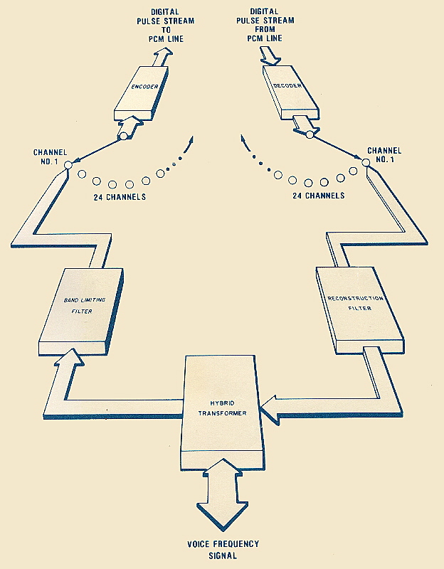
It is a simplified block diagram of one channel's worth of such a terminal, drawn in fanciful perspective form.
Nearest us is the hybrid transformer, which mediates between the "two-wire" audio ("voice frequency", in the telephone terminology of the era) circuit, in which transmission in both directions is over the same physical medium (a single cable pair) and the separate virtual outgoing and incoming channel sides derived by digital technique.
Note that here the 24 audio signals, still in analog form, are time-multiplexed (note the rotary switch metaphor in the illustration), so that a single encode or decode circuit could be shared between all 24 channels.
In the next generation of this kind of equipment (the D5 Digital Channel Bank, actually introduced in 1982), with large-scale integrated circuits available, each "channel unit" filtered, sampled, and encoded a single audio signal, and the resulting digital streams were time-multiplexed.
Best regards,
Doug
• I learned the basic concepts in that context, specifically in the use of digital representation of speech waveform in the telephone network.
• In that context, the implementation completely follows the classical concepts where, for example, in digital photography we use an "incomplete" implementation of the concept.
Of course in these discussions two low-pass filters play prominent roles:
• The band-limiting filter (antialising filter), whose role is to remove from the source "signal" all frequency components at or above the Nyquist frequency, so as to avert "frequency foldover distortion", or "aliasing".
In digital photography, we often do not actually apply this.
• The reconstruction filter, whose job is to extract from the complex spectrum of the reconstructed train of sample pulses just those frequencies below the Nyquist frequency, which together will in fact constitute a reconstruction of the original "signal".In digital photography, we do not actually apply this at all.
A wonderful illumination of this occurs in the cover illustration of the Bell System Technical Journal for November, 1982. That issue was devoted to the then-current family of digital transmission terminals, the D4 Digital Channel Bank family (actually introduced in 1976).
The basic assembly took 24 audio signals, sampled and digitized them, and multiplexed them into a single 1.544 Mb/s digital stream for transmission (perhaps over a physical cable pair), and of course on the receiving side did the opposite.
Here is that cover illustration:
It is a simplified block diagram of one channel's worth of such a terminal, drawn in fanciful perspective form.
Nearest us is the hybrid transformer, which mediates between the "two-wire" audio ("voice frequency", in the telephone terminology of the era) circuit, in which transmission in both directions is over the same physical medium (a single cable pair) and the separate virtual outgoing and incoming channel sides derived by digital technique.
This would not be present if the voice frequency circuit were "four wire", with the two directions of transmission already on physically separate media, as we might have at the interface of a long-distance switching machine.
But just behind we see the two famous filters, two key players in the conceptual level of this drama, "in our face".Note that here the 24 audio signals, still in analog form, are time-multiplexed (note the rotary switch metaphor in the illustration), so that a single encode or decode circuit could be shared between all 24 channels.
In the next generation of this kind of equipment (the D5 Digital Channel Bank, actually introduced in 1982), with large-scale integrated circuits available, each "channel unit" filtered, sampled, and encoded a single audio signal, and the resulting digital streams were time-multiplexed.
Best regards,
Doug