Doug Kerr
Well-known member
This is a second stream of thought about incident light exposure metering.
In incident light exposure metering, we measure a property of the light that illuminates the subject. (I am being intentionally imprecise at this point as to what property that is). It is distinguished from the more-familiar reflected light exposure metering, in which we measure the luminance of the scene (averaged over the field of view, or some part of that, or some region larger than that).
Although we rarely hear it said in this way, the objective of incident light metering is:
That is, it seeks the have the image of a black cat on a coal pile always look like a black cat on a coal pile, not a gray cat on an ash heap (as would typically happen with reflected light exposure metering).
If the entire subject in which we are interested were in a plane, then the property we would want to measure of the incident illumination would be its illuminance upon the plane of the subject.
A photographic exposure (f-number and shutter speed) based on that, taking into account the sensitivity of the film or digital system, will fulfill the objective stated above in blue, regardless of the orientation of the subject plane with respect to the lens axis (assuming that the illuminance was measured as upon that plane), and regardless of the direction from which the illumination came, or how it was composed of illumination from different sources at different angles.
How can we measure the illuminance upon that plane? Imagine a meter that has a flat receptor and responds to the total luminous flux that strikes that its surface. If we go though some neat stuff with a lot of cosines, we will find that the meter's response is proportional to the (average) illuminance upon its receptor. If we position the receptor so it is at the subject (or where the subject will be for the actual shot), and parallel to the plane of the subject, what the meter perceives is the property needed to determine the needed photographic exposure to attain the objective in blue.
Neat! Photographers of billboards or building fronts now know how to proceed.
But not portrait photographers.
If the entire subject does not lie in a plane (a human face decidedly does not, for example), and the illumination is not uniform over all directions of arrival that illuminate parts of the subject that will be included in the shot, there is no photographic exposure that will actually fulfill the objective in blue. Thus in such a case, it would be futile to inquire as to what property of the illumination should we measure to guide the photographic exposure in order to fulfill the objective in blue.
Does this mean that we cannot use exposure metering in such a situation? Not in a definitive way.
If the light comes from two of three discrete sources (three photographic floodlights, for example), could we separately measure the illuminance from each, and adjust that so it was equal for the three sources, and then base our photographic exposure on that value?
Well, luminance must be determined as upon a plane of some orientation. What plane would that be for each of our three floodlights?
Well, from the one aimed at the model's right ear, perhaps the plane of the right side of her face. But the right side of her face is not likely a plane - perhaps more like part of a cylinder.
And in fact let's consider an exposure taken with only this light source in effect (with it set to some arbitrary potency), and let's for the moment imagine that the model's whole face has a uniform reflectance (kabuki makeup, for example).
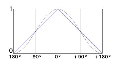
But we find that the luminance of the different parts of the right side of her face will not be uniform. It will be highest for the part (by the ear perhaps) that is (mostly) locally perpendicular to a line from the source - where the luminous flux density of the arriving light causes the greatest illuminance.
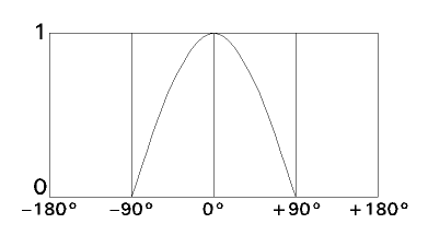
But further to the front (perhaps below her right eye), the light from that source strikes the face "obliquely", thus the illuminance it causes is less, and so so the luminance of the light reflected from it will be correspondingly less. This is in fact the classical "shading" result.
So we can see that there would no plane "against which" we could determine the illuminance from the one light source so that from that measurement we could determine a photographic exposure that would completely fulfill the now infamous blue objective for the right side of the model's head (even if we were willing to make three measurements, one for each light source, to do the total exposure planning job).
[continued]
In incident light exposure metering, we measure a property of the light that illuminates the subject. (I am being intentionally imprecise at this point as to what property that is). It is distinguished from the more-familiar reflected light exposure metering, in which we measure the luminance of the scene (averaged over the field of view, or some part of that, or some region larger than that).
Although we rarely hear it said in this way, the objective of incident light metering is:
To have the exposure result (such as the film density, or the digital representation) for each part of the scene be based on the reflectance of that part of the scene, for any illumination.
That is, it seeks the have the image of a black cat on a coal pile always look like a black cat on a coal pile, not a gray cat on an ash heap (as would typically happen with reflected light exposure metering).
If the entire subject in which we are interested were in a plane, then the property we would want to measure of the incident illumination would be its illuminance upon the plane of the subject.
A photographic exposure (f-number and shutter speed) based on that, taking into account the sensitivity of the film or digital system, will fulfill the objective stated above in blue, regardless of the orientation of the subject plane with respect to the lens axis (assuming that the illuminance was measured as upon that plane), and regardless of the direction from which the illumination came, or how it was composed of illumination from different sources at different angles.
How can we measure the illuminance upon that plane? Imagine a meter that has a flat receptor and responds to the total luminous flux that strikes that its surface. If we go though some neat stuff with a lot of cosines, we will find that the meter's response is proportional to the (average) illuminance upon its receptor. If we position the receptor so it is at the subject (or where the subject will be for the actual shot), and parallel to the plane of the subject, what the meter perceives is the property needed to determine the needed photographic exposure to attain the objective in blue.
Neat! Photographers of billboards or building fronts now know how to proceed.
But not portrait photographers.
If the entire subject does not lie in a plane (a human face decidedly does not, for example), and the illumination is not uniform over all directions of arrival that illuminate parts of the subject that will be included in the shot, there is no photographic exposure that will actually fulfill the objective in blue. Thus in such a case, it would be futile to inquire as to what property of the illumination should we measure to guide the photographic exposure in order to fulfill the objective in blue.
Does this mean that we cannot use exposure metering in such a situation? Not in a definitive way.
If the light comes from two of three discrete sources (three photographic floodlights, for example), could we separately measure the illuminance from each, and adjust that so it was equal for the three sources, and then base our photographic exposure on that value?
Well, luminance must be determined as upon a plane of some orientation. What plane would that be for each of our three floodlights?
Well, from the one aimed at the model's right ear, perhaps the plane of the right side of her face. But the right side of her face is not likely a plane - perhaps more like part of a cylinder.
And in fact let's consider an exposure taken with only this light source in effect (with it set to some arbitrary potency), and let's for the moment imagine that the model's whole face has a uniform reflectance (kabuki makeup, for example).
But we find that the luminance of the different parts of the right side of her face will not be uniform. It will be highest for the part (by the ear perhaps) that is (mostly) locally perpendicular to a line from the source - where the luminous flux density of the arriving light causes the greatest illuminance.
But further to the front (perhaps below her right eye), the light from that source strikes the face "obliquely", thus the illuminance it causes is less, and so so the luminance of the light reflected from it will be correspondingly less. This is in fact the classical "shading" result.
Now let me digress here (before some reader does it for me) to note that this in fact may be just what we want, for some artistic purpose. That's fine. But this does not comport with the objective in blue. And if we do not hold to that, we cannot follow the rest of the trail. So we will hold to that objective as the premise of this part of the work.
So we can see that there would no plane "against which" we could determine the illuminance from the one light source so that from that measurement we could determine a photographic exposure that would completely fulfill the now infamous blue objective for the right side of the model's head (even if we were willing to make three measurements, one for each light source, to do the total exposure planning job).
[continued]