
Doug Kerr
Well-known member
In much or my recent work here on such matters as aliasing in digital photography, I have often introduced each theoretical concept in the context of the digital representation of an electrical waveform, often an audio waveform, and in particular an audio waveform in a telephone transmission system. That is for two reasons:
• The classical model of such a system is much cleaner than the model of a digital imaging system.
• I learned the theory in that context, and taught it for may years in that context!
In any case, great advances in our understanding of the theory of representation by sampling, and in the pragmatic implementation of such, came in connection with the development of digital transmission systems for the telephone network, something that first came into "commercial" us in the United States in 1962.
The November, 1982 issue of The Bell System Technical Journal was entirely devoted to the D4 channel bank. This was the (at the time) latest design iteration of an equipment unit that took 24 "telephone-grade" voice-frequency (audio) signals, with nominal bandwidth 300-3450 Hz, and conveyed them in digital form over a single bidirectional 1.544 Mb/s digital stream.
The cover of that issue is one of my favorite pieces of technical art. It nicely portrays, in a simulated three-dimensional block diagram, seen in a perspective view, a number of the pivotal elements of a digital transmission system.
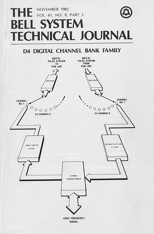
In the foreground we see the hybrid transformer*. This mediates between the "two-wire" paradigm of the telephone line, in which both directions of transmission coexist on the same physical circuit, and the "virtual four-wire" paradigm of the digital system, in which the two directions of transmission are wholly separate (physically, electrically, and logically).
Just "behind" this, we see our two beloved low-pass filters. On the left is the band-limiting filter (the anti-aliasing filter).
Its purpose is to strip from the incoming audio waveform any components whose frequencies are at or above the Nyquist frequency for the sampling rate used here (which is 8000 Hz, so the Nyquist frequency is 4000 Hz). Such components would of course lead to aliasing of the type with which we are most familiar, in which such "rogue" components would be replaced, in the reconstructed waveform, by spurious components having no relationship to the overall waveform.
On the right, we have the reconstruction filter. We think of it (quite aptly) as taking a train of electrical sample pulses (a reproduction, from their digital descriptions, of the sampling pulses drawn from the waveform at the sending end) and from them developing a reproduction of the original waveform itself.
But there is another way to look at the role of this filter: it averts what is called interpolation aliasing (sometimes called, in the context of a sampled photographic image, display aliasing). Thus, we see that the system is symmetrical: every imperative of the sending end has a matching imperative at the receiving end.
But we rarely speak, except in textbooks and learned papers, of interpolation aliasing.
In a recent note here, I pointed out that a significant difference between the "electrical waveform" case and the "photographic image case" is that in the normal execution of the entire digital photographic image "chain" there is no reconstruction filter. The implications of that are described in that other note.
Best regards,
Doug
• The classical model of such a system is much cleaner than the model of a digital imaging system.
• I learned the theory in that context, and taught it for may years in that context!
In any case, great advances in our understanding of the theory of representation by sampling, and in the pragmatic implementation of such, came in connection with the development of digital transmission systems for the telephone network, something that first came into "commercial" us in the United States in 1962.
The November, 1982 issue of The Bell System Technical Journal was entirely devoted to the D4 channel bank. This was the (at the time) latest design iteration of an equipment unit that took 24 "telephone-grade" voice-frequency (audio) signals, with nominal bandwidth 300-3450 Hz, and conveyed them in digital form over a single bidirectional 1.544 Mb/s digital stream.
The cover of that issue is one of my favorite pieces of technical art. It nicely portrays, in a simulated three-dimensional block diagram, seen in a perspective view, a number of the pivotal elements of a digital transmission system.
In the foreground we see the hybrid transformer*. This mediates between the "two-wire" paradigm of the telephone line, in which both directions of transmission coexist on the same physical circuit, and the "virtual four-wire" paradigm of the digital system, in which the two directions of transmission are wholly separate (physically, electrically, and logically).
* At an earlier time, this was called a "hybrid coil" circuit, but "coil" there was an exact synonym for transformer. It is often called today (not by me, unless I'm being very colloquial) just "a hybrid".
Just "behind" this, we see our two beloved low-pass filters. On the left is the band-limiting filter (the anti-aliasing filter).
Its purpose is to strip from the incoming audio waveform any components whose frequencies are at or above the Nyquist frequency for the sampling rate used here (which is 8000 Hz, so the Nyquist frequency is 4000 Hz). Such components would of course lead to aliasing of the type with which we are most familiar, in which such "rogue" components would be replaced, in the reconstructed waveform, by spurious components having no relationship to the overall waveform.
On the right, we have the reconstruction filter. We think of it (quite aptly) as taking a train of electrical sample pulses (a reproduction, from their digital descriptions, of the sampling pulses drawn from the waveform at the sending end) and from them developing a reproduction of the original waveform itself.
But there is another way to look at the role of this filter: it averts what is called interpolation aliasing (sometimes called, in the context of a sampled photographic image, display aliasing). Thus, we see that the system is symmetrical: every imperative of the sending end has a matching imperative at the receiving end.
But we rarely speak, except in textbooks and learned papers, of interpolation aliasing.
The design of the filters in the D4 channel units is a technological tour de force.
In a recent note here, I pointed out that a significant difference between the "electrical waveform" case and the "photographic image case" is that in the normal execution of the entire digital photographic image "chain" there is no reconstruction filter. The implications of that are described in that other note.
Best regards,
Doug